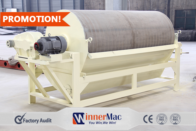
Introduction and function of Magnetic separator
Introduction and function of Magnetic separator
-
Capacity-8-240t/h
-
Product Improvement:
Magnetic system materials adopt ferrite and NdFeB with high performance, high coercive force and high remanence; the surface of the cylinder is lined with our wear-resistant rubber.
Magnetic separation method of magnetic separator , which is based on the difference of mineral magnetic, bearing different forces in the magnetic field of magnetic separator, resulting in material separation. It is mainly used for sorting ferrous metal ores (iron, manganese, chromium); as well as non-ferrous and rare metals. With good separation efficiency, high processing capacity, and high recovery rate, the application of magnetic separation method in the new iron ore dressing plant is very common. Magnetic concentration, as one kind of ore concentration methods, play an important part in varies kinds of mining separation plants.
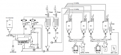
After the primary crushing, grinding and separating processing, The mining powder mixture are fed to the ore magnetic separators. The magnetite particles overcame all mechanical force (such as the gravity, centrifugalforce, friction force, etc) and adhere to the magnetic separator roller because of the magnetic force. Then the magnetite particles will be transported to the discharge opening and separated as the magnetic products. The non-magnetic substance will be discharged from the frame bottom by the mechanical force. To upgrade the final products quality and make full use of the mining ore, the separated particles will be separated by other magnetic separator again for twice or three times.Finally the purified particles will conveyed to the thickener and the dryer for thickening and drying processing.
Working principle and Application field of Magnetic separator
Ore magnetic separation is that materials which is going to be elected bearing the force of magnetic and other mechanical (such as gravity, centrifugal force, friction, medium resistance, etc.) together, in the sorting space of the magnetic separator. The magnetic suffered by mineral grains is related with the size and magnetic of the mineral; non-magnetic mineral particles mainly by mechanical force. Consequently, magnetic mineral particles and non-magnetic mineral particles move along different paths to get separation. In general the magnetic force bore by magnetic particles is proportional to the strength and gradient of the magnetic field.
There is a magnetic field around the magnetic materials. Magnetic field can be divided into uniform magnetic field and non-uniform magnetic field. The strength and direction of various points in uniform magnetic field are in the same size; and the strength and direction in non-uniform magnetic field are always changing. Mineral particles in a uniform magnetic field only by the role of the torque, its long axis parallel to the direction of magnetic field; in the non-uniform magnetic field, the mineral particles not only by the role of the torque, but also by the magnetic force, resulting in mineral particles both rotation and moving to the direction of magnetic field gradient increasing, and being sucked in the magnet surface in the last. Such mineral particles with different magnetic can be separation. Therefore, the magnetic selection is a method based on the differences of permeability between minerals to achieve separation in the non-uniform magnetic field.
There are 2 common types of magnetic separator, they are :
Counter flow type permanent magnetic separator and
Semi-counter flow type magnetic separator
Counter flow type permanent
magnetic drum separator: slurry flows over against drum, which create great conditions for cleaning of non magnetic ores. The non magnetic ores approach the clean surface of drum and the magnetic ores can be absorbed in the strongest magnetic field.
Semi-counter flow type permanent
magnetic drum separator: slurry is fed into cavity from the bottom of drum, and the magnetic ores fall into concentrate tank after reaching a certain height, while the non magnetic ores will enter into tailings tank along with slurry in the opposite direction with drum.
The Technical Parameter of Magnetic Separator:
|
Model |
Cylinder
Dimension
(mm) |
Average value of dressing area
and magnetic induction of the
cylinder surface(mT) |
Cylinder
Revolution
(r.p.m) |
Feeding
Particle
Size
(mm) |
Capacity
(t/h) |
Motor Model |
Motor
Power
(kw) |
Weight
(kg) |
|
CTB-69 |
φ600*900 |
145-180 |
40 |
0~0.2 |
8-15 |
Y90L-4 |
1.5 |
981 |
|
CTN-69 |
φ600*900 |
145-180 |
40 |
0-0.6 |
8-15 |
Y90L-4 |
1.5 |
780 |
|
CTS-69 |
φ600*900 |
145-180 |
40 |
0-6 |
8-15 |
Y90L-4 |
1.5 |
830 |
|
CTB-612 |
φ600*1200 |
145-180 |
40 |
0-0.2 |
10-20 |
JTC561 |
2.2 |
1050 |
|
CTN-612 |
φ600*1200 |
145-180 |
40 |
0-0.6 |
10-20 |
JTC561 |
2.2 |
990 |
|
CTS-612 |
φ600*1200 |
145-180 |
40 |
0-6 |
10-20 |
JTC561 |
2.2 |
960 |
|
CTB-618 |
φ600*1800 |
145-180 |
40 |
0-0.2 |
15-30 |
JTC561A |
2 |
1390 |
|
CTN-618 |
φ600*1800 |
145-180 |
40 |
0-0.6 |
15-30 |
JTC561A |
2 |
1330 |
|
CTS-618 |
φ600*1800 |
145-180 |
40 |
0-6 |
15-30 |
JTC561A |
2 |
1340 |
|
CTB-712 |
φ700*1200 |
155-180 |
35 |
0-0.2 |
15-30 |
JTC562A |
2.8 |
1510 |
|
CTN-712 |
φ700*1200 |
155-180 |
35 |
0-0.6 |
15-30 |
JTC562A |
2.8 |
1500 |
|
CTS-712 |
φ700*1200 |
155-180 |
35 |
0-6 |
15-30 |
JTC562A |
2.8 |
1460 |
|
CTB-718 |
φ700*1800 |
155-180 |
35 |
0-0.2 |
20-45 |
JTC562A |
2.8 |
1579 |
|
CTN-718 |
φ700*1800 |
155-180 |
35 |
0-0.6 |
20-45 |
JTC562A |
2.8 |
1579 |
|
CTS-718 |
φ700*1800 |
155-180 |
35 |
0-6 |
20-45 |
JTC562A |
2.8 |
1579 |
|
CTB-918 |
φ900*1800 |
165-180 |
28 |
0-0.2 |
25-55 |
XWD4-7-35 |
4 |
4000 |
|
CTN-918 |
φ900*1800 |
165-180 |
28 |
0-0.6 |
25- 55 |
XWD4-7-35 |
4 |
4000 |
|
CTS-918 |
φ900*1800 |
165-180 |
28 |
0-6 |
25-55 |
XWD4-7-35 |
4 |
4000 |
|
CTB-930 |
φ900*3000 |
165-180 |
28 |
0-0.2 |
52-100 |
XWD5.5-7-43 |
5.5 |
4280 |
|
CTN-930 |
φ900*3000 |
165-180 |
28 |
0-0.6 |
52-100 |
XWD5.5-7-43 |
5.5 |
4280 |
|
CTS-930 |
φ900*3000 |
165-180 |
28 |
0-6 |
52-100 |
XWD5.5-7-43 |
5.5 |
4280 |
|
CTB-1018 |
φ1050*1800 |
165-180 |
20 |
0-0.2 |
40-80 |
YCT280-5.5-19.2 |
5.5 |
3807 |
|
CTN-1018 |
φ1050*1800 |
165-180 |
20 |
0-0.6 |
40-80 |
YCT280-5.5-19.2 |
5.5 |
3807 |
|
CTS-1018 |
φ1050*1800 |
165-180 |
20 |
0-6 |
40-80 |
YCT280-5.5-19.2 |
5.5 |
3807 |
|
CTB-1021 |
φ1050*2100 |
165-180 |
20 |
0-0.2 |
40-80 |
XWD5.5-7-43 |
5.5 |
3921 |
|
CTN-1021 |
φ1050*2100 |
165-180 |
20 |
0-0.6 |
40-80 |
XWD5.5-7-43 |
5.5 |
3921 |
|
CTS-1021 |
φ1050*2100 |
165-180 |
20 |
0-6 |
40-80 |
XWD5.5-7-43 |
5.5 |
3921 |
|
CTB-1024 |
φ1050*2400 |
165-180 |
20 |
0-0.2 |
52-100 |
XWD5.5-7-43 |
5.5 |
4404 |
|
CTN-1024 |
φ1050*2400 |
165-180 |
20 |
0-0.6 |
52-100 |
XWD5.5-7-43 |
5.5 |
5132 |
|
CTS-1024 |
φ1050*2400 |
165-180 |
20 |
0-6 |
52-100 |
XWD5.5-7-43 |
5.5 |
4628 |
|
CTB-1030 |
φ1050*3000 |
160-180 |
20 |
0-0.2 |
120-200 |
XWD7.5-7-43 |
7.5 |
4431 |
|
CTN-1030 |
φ1050*3000 |
160-180 |
20 |
0-0.6 |
120-200 |
XWD7.5-7-43 |
7.5 |
4431 |
|
CTS-1030 |
φ1050*3000 |
160-180 |
20 |
0-6 |
120-200 |
XWD7.5-7-43 |
7.5 |
4431 |
|
CTB-1218 |
φ1200*1800 |
165-180 |
19 |
0-0.2 |
130-140 |
XWD5.5-7-43 |
5.5 |
5800 |
|
CTN-1218 |
φ1200*1800 |
165-180 |
19 |
0-0.6 |
130-140 |
XWD5.5-7-43 |
5.5 |
5800 |
|
CTS-1218 |
φ1200*1800 |
165-180 |
19 |
0-6 |
130-140 |
XWD5.5-7-43 |
5.5 |
5800 |
|
CTB-1221 |
φ1200*2100 |
165-180 |
19 |
0-0.2 |
55-110 |
XWD7.5-7-43 |
7.5 |
5800 |
|
CTB-1224 |
φ1200*2400 |
165-180 |
19 |
0-0.2 |
100-190 |
XWD7.5-7-43 |
7.5 |
6200 |
|
CTN-1224 |
φ1200*2400 |
165-180 |
19 |
0-0.6 |
100-190 |
XWD7.5-7-43 |
7.5 |
6200 |
|
CTS-1224 |
φ1200*2400 |
165-180 |
19 |
0-6 |
100-190 |
XWD7.5-7-43 |
7.5 |
6200 |
|
CTB-1230 |
φ1200*3000 |
165-180 |
19 |
0-0.2 |
130-240 |
XWD7.5-7-43 |
7.5 |
7200 |
|
CTN-1230 |
φ1200*3000 |
165-180 |
19 |
0-0.6 |
130-240 |
XWD7.5-7-43 |
7.5 |
7200 |
|
CTS-1230 |
φ1200*3000 |
165-180 |
19 |
0-6 |
130-240 |
XWD7.5-7-43 |
7.5 |
7200 |
|
CTB-1530 |
φ1500*3000 |
170-200 |
19 |
0-6 |
170-280 |
XWD7.5-7-43 |
11 |
8000 |